Functional Description

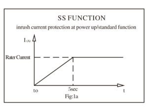
1. SS function (soft start function)

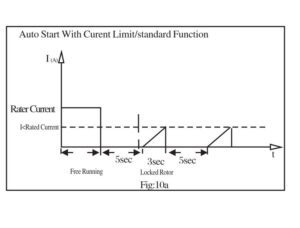
When the power switch is turned on to supply current to the fan, the current is zero and starts to increase gradually until the fan has achieved its maximum speed and the rated current. The maximum current at start up is equal to the free running current (or less in case the rotor is locked at start up). The fan will achieve the rated speed within 5 seconds (see Fig. 1a).

ss function
2. LP function (Locked rotor protection and restart with Current Limit).

Auto Start function ensures that the fan motor will automatically restart in case the blade is blocked and then it is released. When the rotor is locked, the fan current is reduced to zero and the fan is trying every 5 seconds to restart with soft start by reverting to the LP function (see Fig. 2a).

3. FG function (Frequency Generator or Tachometer Output) {YELLOW wire}

This is an open collector output which provides a square wave signal if this open collector output is connected to a “PULL UP” resistor and is powered by the power supply voltage which is compatible with the input of the reading device (such as TTL input of the computer etc.). The maximum collector voltage maybe up to 72VDC and the maximum collector current is 10mA. The power supply of the reading device must have the same ground potential as the fan (see Fig. 3a and Fig. 3b).

4. RD function (Rotation Detection function) {GRAY wire}

This is an open collector function with the same hardware as the FG function mentioned above. The output signal is LOW when the fan is Rotating and it is set HIGH when the fan is stopped or it is powered OFF (see Fig. 4a).

5. RDb function (complement of Rotation Detection Signal) {VIOLET wire}

This is an open collector function with the same hardware as the FG function mentioned above. The output signal is HIGH when the fan is Rotating and it is LOW when the fan is stopped (see Fig. 5a). This output can be connected in parallel to the RDb of an array of fans ending to a single alarm device to warn in case any one fan has stopped.

6. LD  function (Life Detection Function) {BROWN wire}

This is an open collector function with the same hardware as the FG function mentioned above. The output signal is LOW when the fan is rotating normally and it is HIGH when the fan speed is rotating below 70% of its rated target speed. The reasons of slow rotation maybe aging or reduced power supply voltage (see Fig. 6a).

7. OVP function (Over-Voltage protection) {Built in, no wire indication}

This function detects the power supply voltage and allows operation up to the
rated maximum operating voltage. Typically the maximum operating voltage (unless otherwise specified) is 20% over the specified rated voltage. If the power supply voltage increases over the 20% limit the fan will stop running and the power supply current will be reduced essentially to zero. The maximum over-voltage protection range is twice the value of the rated voltage. For example if the rated voltage is 24V, the maximum voltage that can be applied accidentally is 48V. Likewise for a 12V fan the maximum applied over-voltage is 24V (See Fig.7a).

8. TC function (Automatic Temperature Control) {GREEN wire}

When this function is applied, the upper and lower temperatures may be selected as well as the choice of maintaining minimum RPM below the minimum temperature chosen. The CS (constant speed), SS (soft start function) and CL (Current Limit) functions are included. The three common control methods are shown in the graph below.

9. RC function (Manual Variable Resistor Control) {ORANGE wire and WHITE wires}

With this function the speed can be controlled using an external variable resistor. This resistor may have any maximum value from 10K to 100K. The fan speed will vary linearly and is proportional to the % change of the resistor value, corresponding to the same % change of the maximum speed. The CS (constant speed), SS (soft start function)  and CL (Current Limit) functions are included. The three common control methods are shown in the graph below.

10. CL function (Current Limit under locked rotor is “built in” no wire indication)

With this function the current is limited during the restart period. (See Fig. 10a).

11. FIXED CS function (Constant Speed is “built in” and is standard, no wire
indication)

This is a very important function because it allows the fan motor to operate safely over a very large power supply voltage range. For example if the fan motor is designed to run at 4200 RPM at the rated voltage of 48 Volts, the fan motor will maintain the same RPM even when the supply voltage varies from 48 to 72 volts. The fixed CS function is preset internally and the maximum RPM is the rated RPM. (See Fig. 11a)

12. VC function (DC Voltage Signal Control) {WHITE wire}

With this function the speed can be controlled by applying an external DC
Voltage signal. This voltage input “Vin” may have any value from 1V to 10 V
(standard value is 1 to 5V). The fan speed will vary linearly and is proportional
to the % change of the “Vin” value, corresponding to the same % change of the
maximum speed. The CS (constant speed), SS (soft start function) and CL
(Current Limit) functions are included. The three common control methods are shown in the graph below.

13. CC  function (Current Source Signal Control) {WHITE wire}

With this function the speed can be controlled by applying an external Current Source Signal. This current input “Iin” may have any value from 4 mA to 50 A(standard value is 4 to 20mA). The fan speed will vary linearly and is proportional to the % change of the Iin value, corresponding to the same % change of the maximum speed. The CS (constant speed),SS (soft start function) and CL (Current Limit) functions are included. The three common control methods are shown in the graph below.

14. PWM function (Pulse Width Modulation Signal Control) {BLUE wire}

With this function the speed can be controlled by applying a pulse width modulated signal whose frequency maybe in the range of 30 Hz to 30 KHz and the max. pulse height “HIGH” maybe from 3 V to 10 V. The maximum pulse height “LOW” is 0.8 V. The fan speed will vary linearly and is proportional to the % change of the Duty Cycle value, corresponding to the same % change of the maximum speed. The CS (constant speed), CC (Soft start function) and CL (Current Limit) functions are included. The three common control methods are shown in the graph below.

Fan structure diagram

Product naming rules